




Getting Started
Having resolved the 'what am I going to build' bit, then the next stage was to plan the actual layout. Up until this point I only had a vague idea of the size it would be and how it would all fit!
Eventually I decided on a U shape and the plan above was drawn up - the final size of the layout is 3.9M wide for the long (canal) section and the right hand leg (for the station area) is 2.7M, with the smaller leg which holds the fiddle yard over my workbench at 2.2M. This last bit was dictated by the door position!
Drawing it out
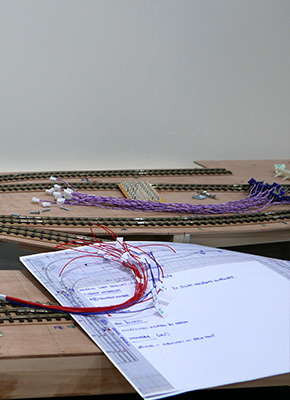
I drew the initial plan on A1 paper using scaled down images of the Peco point templates, until I got something that I thought should work. Things have changed a little from the plan shown with the canal basin included, but extended and the proposed route for the canal, removed. Happy with that, I moved on and drew it all out full size on sheets of A1 paper joined together, with it laid out flat on the study floor. Scale plans look great, but it's not until you get the full size thing together that you know if it will work (particularly the curves) and that the points will all fit how you expected them too.
In 7mm scale even 3.9M isn't that sizeable, but narrow gauge does mean tight corners are possible (within reason) and with careful working on the scenery and placement of buildings it helps to improve the illusion!
What I have is a small station with an island platform and headshunt so locos can run round trains, a couple of goods sidings that need some thought getting in to and the same for the loco shed. I have a lower level track that drops down from the station to a canal section for goods transfer, plus a warehouse siding. Continuing on it goes into a deep cutting and ends up in the fiddle yard. The upper line from the station climbs quite steeply, hidden between buildings and a high level scenic area, to run along the back part hidden by trees and foreground buildings, which makes it less obvious. It too drops down into a cutting and ends up in the fiddle yard. Trains from here can go back out on either level. It gives enough scope for some interesting train movements.
Thankfully it only needed a little tweaking whilst track was being laid!
Baseboards
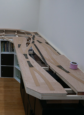
I decided that as it was never going to leave the room it is in, i would use an open 'L' girder construction for the baseboard. The trackbed is 10mm plywood raised on cross-bearers to accomodate the changing track heights and gradients.
The rear 'L' girders are bolted to the walls, with the front supported all round with ply cross-bearers resting on storage cupboards / bookcases. There is a gap of about 150mm so I can get access under the layout for wiring and sorting out things like servos. It's not easy, but possible!
Baseboard height is set at 1.2M which means that you are looking in to the scene rather than down onto it. Seems more natural. It is also a nice working height, except for the areas I ought to have foreseen and that's the corners. Because of the height it's not possible to reach the far corners without use of a set of steps! Not good for the back.
Control
The original layout was planned for and executed with straightforward DC operation. At the time, DCC was considered as unnecessary, plus I was unsure that I would be able to squeeze decoders into some of the locos.
Fast forward a few years to 2020 and lockdowns. With plenty of time on hand, some experimentation with DCC and a decision was made to change - the layout is now able to operate in either DC or DCC mode. In practice only DCC gets used these days.
More on this in the Controls section