

Laying the Track
To Make or Buy?
I did consider constructing the track myself, using either copperclad sleepers with soldered construction, or a similar method to P4 that I looked at, using wooden sleepers and copper rivets. For practical reasons and this being my first real layout for over 40 years, I sensibly decided to use the Peco 0-16.5 track, feeling sure that I could disguise its look well enough once laid.
Modifying Peco Points
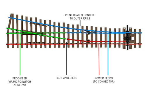
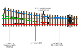
Although the Peco O-16.5 points are designed with 'live frogs', they do really need to be modified before use.
For more information, please click on the link below -
Track Fixing
I fixed the track on to 3mm cork, pinned down using track pins. None of the track is glued, but as the track-base is either 6mm or 10mm plywood it won't be moving! Extra pins were used on the tighter bends to ensure it kept its shape.
Power feeds have been soldered to the underside of the rails as it was laid. These feed wires are then taken to connector blocks fixed under the baseboards. These are all numbered, as are the power-feed wires coming from the control panel.
All of the sidings have isolating sections, created by introducing isolated joiners in one of the rails. This could be essential for DC operation, for 'parking' a loco!
The track on Meifford is not level all the way round.Starting from station area, the level drops down about 35mm to the small goods sidings and then again from there it drops by about 20mm down to the engine shed. Whilst laying the track, it is important to use a wagon to check the smooth running, particularly through points as well as any curves and to make sure track joints are smooth.This was very important as some (several) of my points are at the start of a slope!
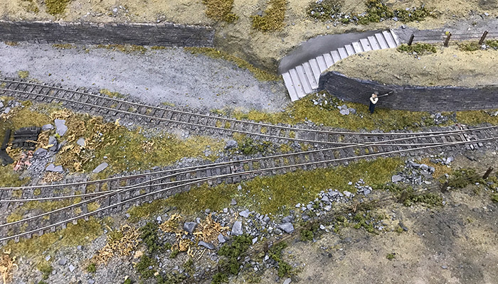
The image below shows one of the points and some track pinned in place. The modifications and wiring of the point are just visible.
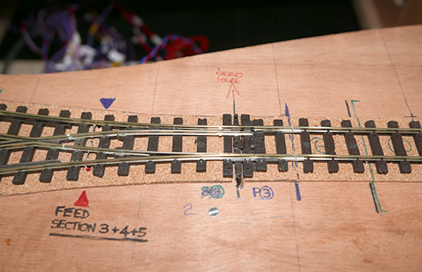
It goes without saying too, that once it is all laid and wired up, it should be tested for operation and electrical continuity. Once it has all been ballasted and the scenery built round (or over) the track, any problems found will be hard to put right. I spent some time doing this, using a variety of locos, just to be sure!
Track Painting and Ballasting.
I know that painting everything in the obligatory 'track colour' paint would seem to be the norm, but I don't think it looks right. I paint everything in a dark grey, that's the sleepers and the sides of the rails. Take a look at real track, it's not all rusty and brown, but more on the 'dirty' side.It's important that the sleepers and all of the visible sides of the rail be covered, except of course be careful with points to ensure the blades seat properly and that paint doesn't impede electrical contact.
Track with a coat of grey paint!
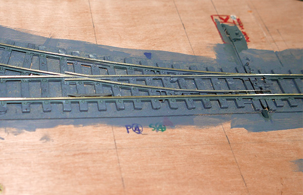
After the dark grey coat, then we can paint on a rust wash to rails. I also airbrush a couple of 'dirt' coats onto the track, using a dark brown mix and then a black mix - spray these a bit 'dry' and don't overdo it. It may be best to wait until after ballasting for this part as it can get the dirty treatment at the same time!
Ballast
As the Meifford Light Railway is somewhat cash-strapped, track maintenance isn't what it could be and indeed ballast is a bit of a mixture of whatever they could find and it would appear somewhat thin in places, plus it seems like some slate has become mixed in with it all. Hasn't caused any accidents, so we won't say much about it!
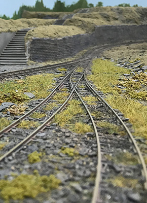
After everything - an example of the ballasted track
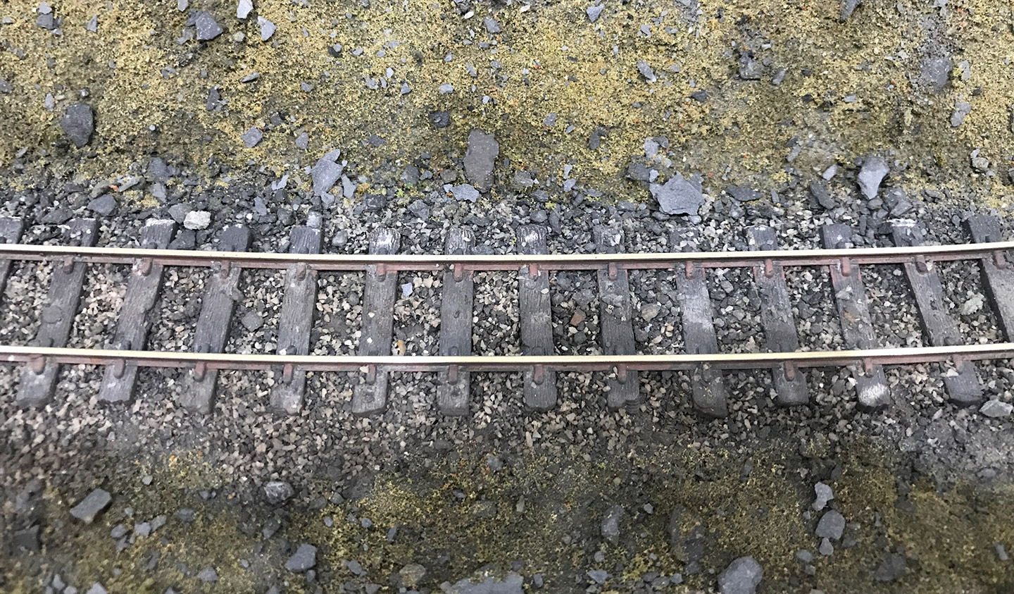
With the nature of the location, I actually left the ballasting until after the scenic work was complete in building the terrain up around the track. For more information, see the scenery section and 'ground cover' for my Light Railway mix!